


Thermowells are tubular housings in which temperature sensors are installed in industrial processes. It is made up of a tube which is drilled and machined from a solid bar stock which is closed at one end and mounted in process stream. Sensors such as Thermocouples and RTD’s are inserted through the open end of the thermowell and are placed at the tip of the closed end. The open end is usually outside the process piping. The heat from the Process fluid is transferred to the Thermowell walls and then to the sensor, so the thermowell is heated up before the sensor. Due to this increase in thermal mass the response of the sensor is slowed down. The construction and specifications of the Thermowell are governed by an International Standard made my ASME (American Society for Mechanical Engineers) called PTC 19.3 TW.
What is PTC 19.3TW ?
PTC means Performance Test Codes, these are some standard experimented series of tests and calculations which are carried out to determine the reliability and workability of a product. PTC 19.3 TW is a standard which is defined for Mechanical designing of a thermowell. This standard simulates various possible scenarios in which a thermowell is subjected, and according to those applications it states possible Thermowell designs which will satisfy the needs without any failure. Currently PTC 19.3 TW 2016 version is used which is a revision from PTC 19.3 TW.
Types of Thermowell:
-
On the basis of Shank design
- Straight Shank Thermowell: These type of thermowells have a constant shank diameter throughout. They have high mechanical strength as there are no altercations made to solid structure of the bar stock. They also possess a decent Response but is still less than the other types.

- Tapered Thermowell: These type of thermowells have a uniformly tapered shank diameter from Root to the Tip, giving least diameter at the Tip. The lower thermal mass at the tip provides a faster response than the Straight Shank.

- Step Shank Thermowell: These type of thermowells have a stepped design with 2 diameters between the Root and the Tip, with lower diameter at the tip portion. These provide the fastest response among all the types. But in terms of mechanical strength these have the lowest strength as due to the addition of a step we have increased the number of failure points.

-
On the basis of mounting
- Threaded Thermowell: In this type of thermowell, Male threads are provided above the root which is directly mounted with the female threads on the process connection.

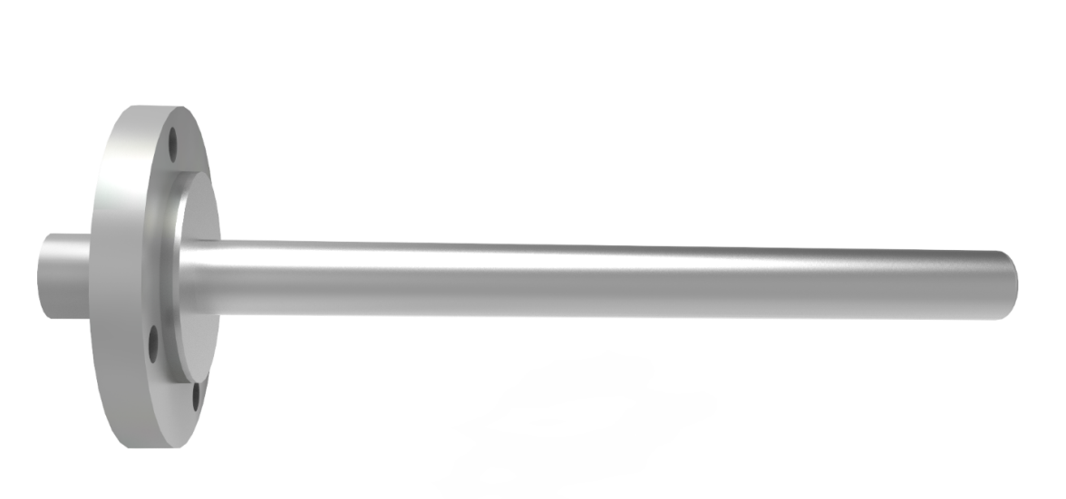
- Flanged Thermowell: In this type of thermowell, a flange is welded or machined above the root of the thermowell. This flange contains mounting holes or threads which are used to mount the thermowell to the process.

- Socket Weld Thermowell: This type of thermowell is mounted using a weld collar which is welded on to the thermowell as well as the process connection.

- Welded Thermowell: In this type the thermowell is directly welded on to the process connection.

- Lap Joint (Van Stone) Thermowell: This type of thermowell is specially used in Pipe standoffs where a mounting flange is already present on the process connection. A small collar is machined on the thermowell by which the thermowell is placed on the flange, and then a counter flange is bolted from above to rigidly mount the thermowell.

-
Special Thermowells
- Thermowells with Velocity Collars: When mounting a thermowell through a pipe standoff the insertion length is increased due to the extended Nipple from the pipe, due to which the thermowell does not pass according to normal standards. So to decrease the unsupported length collars are provided on the thermowell which has to be closed fit with the pipe standoff. By doing this we decrease the unsupported length which increases the stability of thermowell inside the flow stream. Sometimes more than one collar is required according to the length of standoff.

- Thermowells with Helical Strakes: In some cases helical strakes can be machined on the thermowell at the insertion length. These helical strakes obstruct the formation of vortices behind the thermowell which decreases the stresses caused due to vortex shedding. This style of design is usually found in Long Chimneys due to the presence of high velocity air currents on higher altitude. Similar concept can be implemented on to Thermowells

Dimensional Specifications Acc. to ASME PTC 19.3 TW 2016:
For Straight & Tapered Thermowells:
| Description | Symbol | Min | Max |
| Unsupported Length | L | 63.5mm | 609.6mm |
| Bore Diameter | d | 3.175.m | 20.955mm |
| Tip Diameter | B | 9.2mm | 46.5mm |
| Taper Ratio | B/A | 0.58 | 1 |
| Bore Ratio | d/B | 0.16 | 0.71 |
| Aspect Ratio | L/B | 2 | – |
| Min Wall Thickness | (B-d)/2 | 3.00mm | – |
| Tip Thickness | t | 3.0mm | – |
For Step Shank Thermowells
| Description | Symbol | Min | Max |
| Unsupported Length | L | 127 mm | 609.6mm |
| Bore Diameter | d | 6.1m | 6.7mm |
| Step dia ratio For B=0.5 inch |
B/A | 0.5 | 0.8 |
| Step dia ratio For B=0.875 inch |
B/A | 0.583 | 0.875 |
| Length Ratio | Ls/L | 0 | 0.6 |
| Min wall tickness | (B-d)/2 | 3mm | – |
| Tip Thickness | t | 3mm | – |