


Flare Stack Monitoring System
Introduction:
Petrochemical and some other industries generate toxic gases as their by-products which cannot be released into atmosphere directly due to environmental and health hazard. These gases needs to be burnt off before they enter the atmosphere. To do so chimneys are equipped with burners which continuously burns these toxic gases. And as this process is very critical in nature Government and Environmental authorities regulate strict laws to continuously monitor this process and have fault detection and control mechanisms in place to ensure smooth running of the system.
There are several types of flare detection systems which is used by the industry like Thermal Imaging, Pyrometer and Thermocouples etc. The best suitable and efficient solution for flare stack monitoring is Thermal Imaging as it has the ability to monitor the flame from a distance without direct contact to the flame and Thermal Imaging gives the additional benefit of viewing the flame in the control room.
In earlier times only the detection of flame was required for this application, but recently due to enhanced safety protocols and government regulations the temperature of the flame is also measured. Some of these toxic gases are not burnt completely unless the flame is at or above a specific temperature. Thermal Imaging system efficiently detects the mail flame as well as the pilot flame and also measure the temperature of the flame continuously to ensure that the gases are completely burnt away.
In some cases additional safety features like explosion proof protection, Enclosure cooling, air purging for dust accumulation can also be implemented in the same system if the userrecommends the same.
System Composition:
A Thermal Imaging flare stack system comprises of the following components.
- High Resolution Thermal Imaging Camera (640 x 480 or 384 x 288 pixels)
- Telescopic lens for long distance imaging (Fixed focus or zoom lenses)
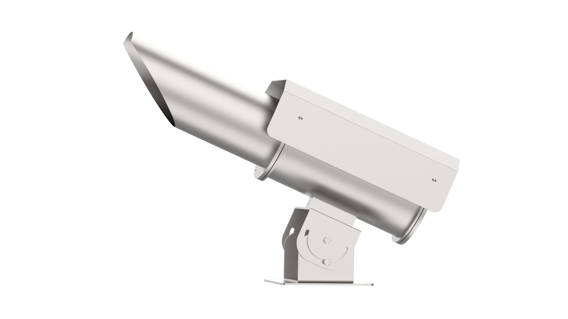
- IP 65 Stainless steel Weather Proof enclosure for Camera with Sunshield.
- ~75° Tilt adjustable mounting capable of fine angular adjustments.
- Windows based PC with InfraViewTM
- I/O Module for Analog and Digital outputs.
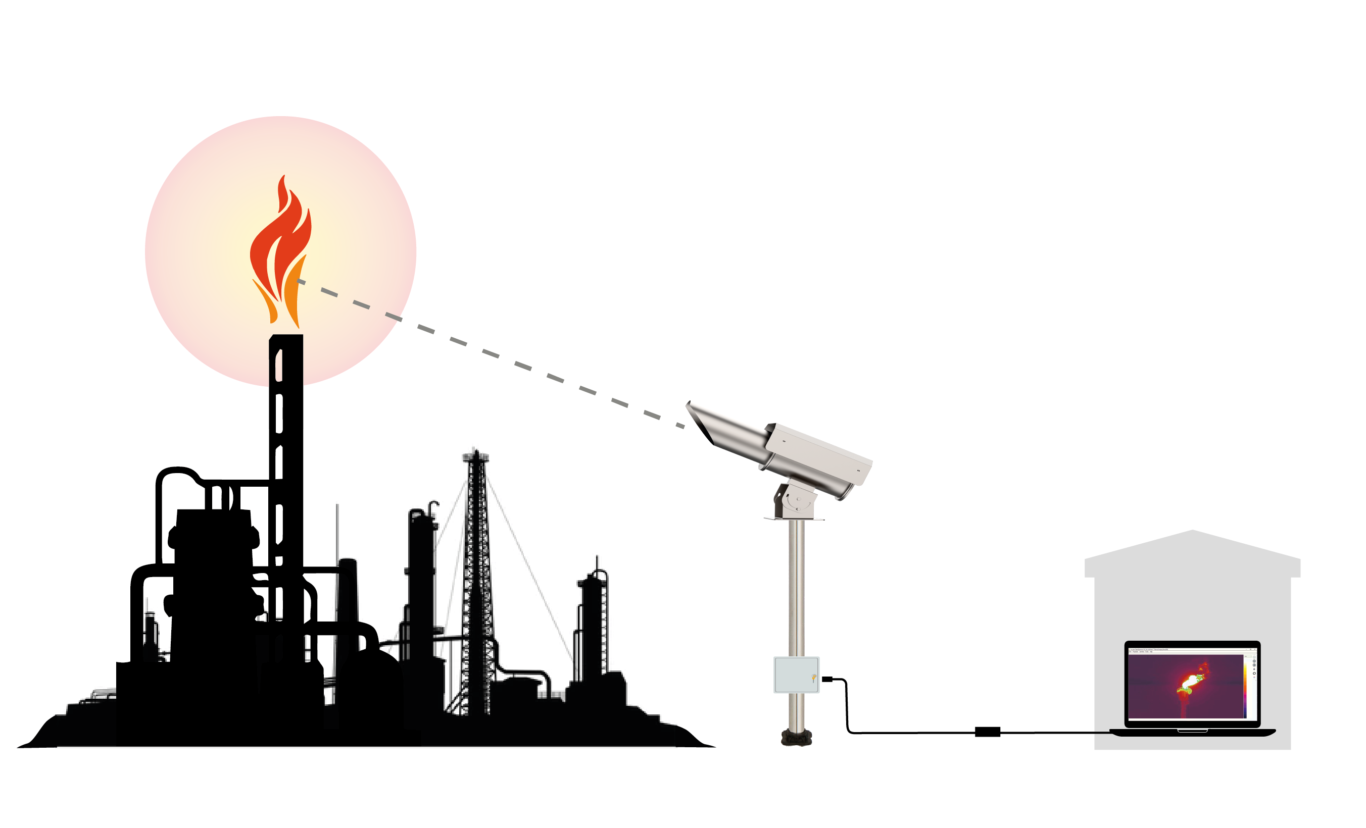
In a basic thermal Imaging flare stack monitoring system the Thermal Imaging camera is coupled with a telescopic lens of 100 mm or higher Focal length and is put inside a weather proof stainless steel enclosure to protect the camera from dust, rain, sunlight etc.
The camera runs on 12VDC Power which can either be supplied directly into the enclosure or suitable power adaptors can be used to convert 220/110 VAC to 12VDC.
The angle of the camera then has to be adjusted using the tilting mechanism provided with the camera enclosure. The camera needs to face the flare stack directly for best results.
The camera hasGigabit Ethernet output which needs to be connected to a PC kept inside the control room or any other specified location.
The Gigabit Ethernet connection can either be laid directly from camera to PC if the distance between the camera and PC is less than 100 meters. In case the distance is larger a Fiber Optic connection can be established between camera and PC.
An additional IO module can also be connected using an Ethernet switch to get Analog and digital outputs. These outputs can be triggered either when the flame is extinguished or the user can get continuous temperature reading in 4-20mA format.
In the PC the user will need to install InfraViewTM Software for Thermal Data acquisition.
Apart from this the software also has the following features.
- Displays Real-time Thermal Video.
- Real Time hot/cold spot detection
- Generate Alarms as burner flame is not detected
- Zoom In/Out function
- Region of Interest
- Live and History Mode
- Trending Analysis & report generation
- Storing video in RAW/MP4 format (Optional)
- Multiple Color Palettes
- Graphical indicator for every ROI.
The software is compatible with Windows 10 Pro system with Intel i5 8th gen or higher 8 GB Ram and storage as per requirement.
How the system works:
- Thermal camera should be mounted on a pedestal aiming directly at the flare stack.
- The thermal camera pointed at the flare stack receives continuous thermal video at 30fps which is processed in the PC using InfraViewTM
- Once the camera and software are connected the flame will be visible in the screen.
- In the screen the user can draw regions of interest. For example the user can draw a rectangle where the flame is visible and could put a threshold temperature to that region of interest.
- So if in any case the flame temperature goes below the threshold temperature or if the flame is completely extinguished the software will generate an alarm.
- Apart from this the user can also get continuous temperature data using 4-20mA output from the IO module.
- The user can use these outputs to monitor the flame continuously and can take required action if the flame is extinguished.
Advantages of Thermal Imaging Flare Stack Monitoring:
- Continuous and Real time monitoring ensuring minimal risk.
- Able to monitor flame through dust, rain, smoke and fog.
- Instant alarms and notifications when the flare is extinguished or the temperature of flame is dropped.
- Provides temperature readouts and visual monitoring feature for ease of use.
- System is designed to work in harsh environmental conditions
- Can be easily integrated to existing plant network.