Introduction to Pellet Plant
Iron ore pellets are spheres to be used as raw material for blast furnaces. They typically contains Fe and various additional material adjusting the chemical composition and the metallurgic properties of the pellets. Typically limestones, dolomite and olivines are added and bentonite is used as binder.
The iron ore pelletizing process consists of three main steps:
- Pelletizing Feed Preparation and Mixing: The raw material (iron ore concentrate, additives—anthracite, dolomite—and binders are prepared in terms of particle size and chemical specifications, dosed, and mixed together to feed the pelletizing process.
- Balling Process: The green pellet is the rolled pellet without any thermal process. It is obtained under strict control of moisture and has a spherical shape and diameter of 8–16 mm.
- Kiln/Induration Process: The green pellets are hardened in a high temperature processing at controlled heating rates, and aim
Kiln Based Process
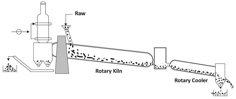
The process of pelletizing combines mixing of the raw material, forming the pellet and a thermal treatment baking the soft raw pellet to hard spheres. The raw material is rolled into a ball and fired in a Rotary kiln to sinter the particles into a hard sphere. In this process thermocouples are installed for temperature monitoring, S-type T/C before Kiln inlet, K-type T/C at Kiln outlet. Max temp. goes upto 1200°C during the process.

S Type Thermocouple
- S-type TC with Thermowell with Adj. C.S Flange.
- Ÿ Outer & inner protection tube KER 710.

K Type Thermocouple
- K-type TC with Thermowell with Adj. C.S Flange.
- Ÿ T-Well (OD x ID) :(22×14) mm Drilled Bar Stock.
- Ÿ Outer Sheath- SS 310.

Indurating Furnace Process
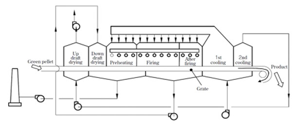
Indurating Furnaces are rectangular/ oval shaped furnaces and are specifically used to produce iron ore pellets. Raw pellet needs to be baked to give them sufficient mechanical strength to withstand further handling during transportation and charging to a blast furnace or to a direct reduced iron furnace.
In an Indurating Furnace, the pellets are loaded on to a travelling grate where they are preheated to 900 degC,before entering into the furnace where the temp. is around 1350degC.
#Multiple B type thermocouples are installed on either side of the furnace for temperature measurement.
#S type thermocouples are also used on the burner top and side to monitor the injection limit.
B/S type thermocouples with Super Kanthal outer tube was installed on either side of the furnace for temperature measurement

K Type Thermocouple
- K-type TC with Thermowell with Adj. C.S Flange.
- Ÿ T-Well (OD x ID) :(22×14) mm Drilled Bar Stock.
- Ÿ Outer Sheath- SS 310.

Schematic Diagram Of Indurating Furnace


Thermocouple Technical Specification
- Element : B/S type, recommended 0.50 or 0.45mm.
- Inner protection tube : 99.7% Recrystallized Alumina KER-710.
- Outer tube : Recrystallized Alumina 99.7% KER710.
- Insulating Tube : Recrystallized Alumina 99.7% KER-710. 2hole/4hole.
- Holding tube : S310
- Process Connection : Adjustable compression fitting or flange.
- Head : Die cast aluminum, Ingress Protection IP67.
B-type T/C

S-type T/C


