


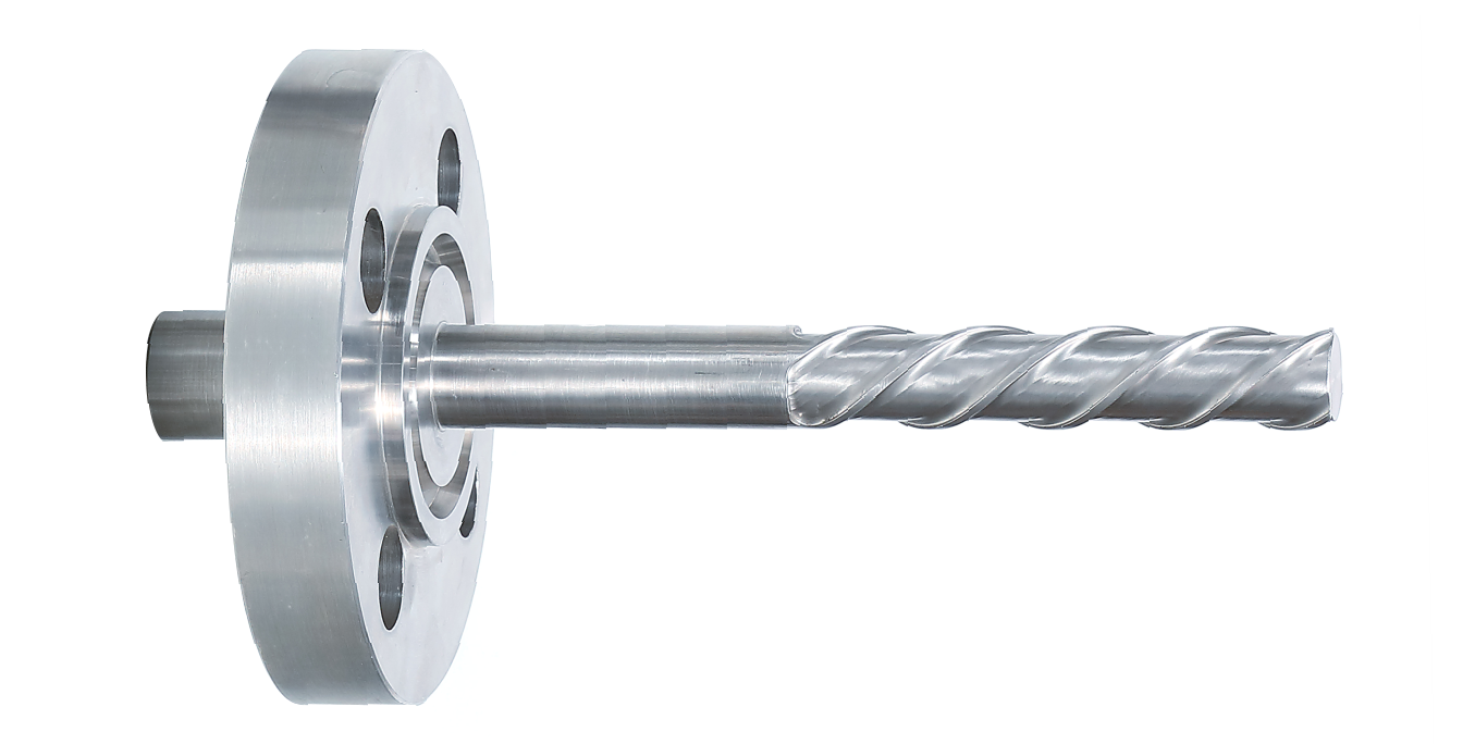
Tempsens has developed a design of thermowell with helical strakes that would remove flow-induced vibrations, enabling more accurate and reliable results of thermowells in service, thereby overcoming the risk of thermowell failures.
The forces potentially causing harmful oscillations on a thermowell stem when immersed in a flowing fluid are associated with vortex-induced vibrations. As the fluid velocity is increased, the rate of vortex shedding increases linearly and the magnitude of the forces increase with the square of the fluid velocity. The thermowell responds elastically according to the force distribution, thereby providing the equivalent elastic strain plot.
This report is intended to present that the thermowell with helical strakes demonstrates no regular vortex shedding (Figure 5.6) as compared to classical thermowell (Figure 5.5). The plots showing flow streamlines provided excellent visualization of the influence of the helical strakes.
It is conducted with the suggestion that the strakes sufficiently disturb the flow in the wake region such that no vortex can form. The strakes also encourage cross-plane flow behaviour along the thermowell length to an extent that was not observed with the classical thermowell, thus interfering with the vortex formation.
Tempsens has proven through physical testing along with Static Structural and CFD analysis of thermowells to be the more reliable and accurate solution by significantly reducing the vibrations and deformation failures along with the reduction in effects of vibration-induced vortices of thermowell.
This report presents a comparative Static Structural analysis. Two distinct time-independent studies have been conducted: one for a standard smooth cylindrical thermowell and one for a thermowell equipped with helical strakes. The report outlines the procedures adopted and the result
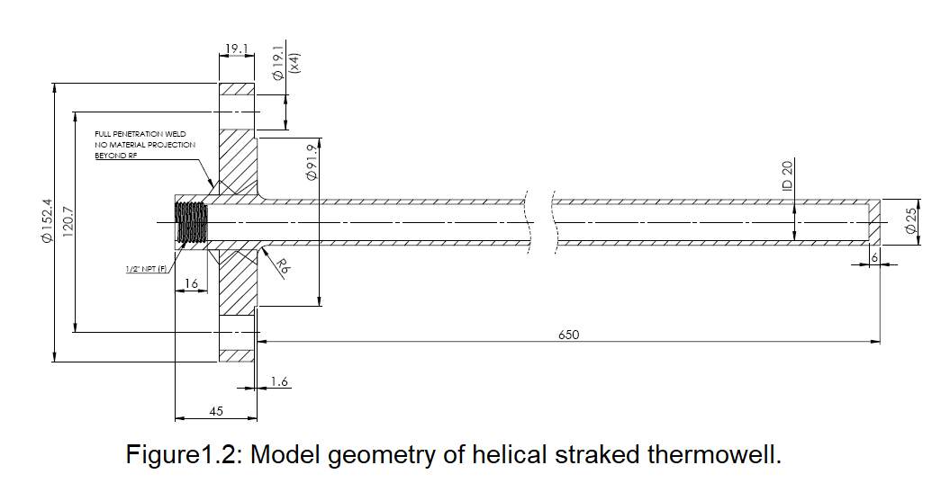
Model Geometry:
The geometries were developed as three dimensional, solid models. Figure 1.1 and figure 1.2 shows the two-dimensional geometry used classical thermowell and helical straked thermowell respectively. The thermowell is welded to a 2” 150# ANSI B16.5 standard flange. The suspended length or the length below the RF of the flange in both the cases is taken as 650mm as shown in figures. In the case of straked thermowell, the helical strakes start from 450mm from RF of the flange. The helical strakes are situated at an angle of 120˚ from each other and are at a pitch of 125mm.
Material Properties for Analysis:
| Material | Elastic Modulus (MPa) | Allowable Stress
(MPa) |
Yield Strength (MPa) | Density (Kg/m3) | Poisson’s Ratio |
| SS316 | 165.0 e+03 | 76.0 | 114.0 | 8030.0 | 0.31 |
SIMULATION ANALYSIS
3D CAD model:
Three-dimensional models of classical thermowell and straked thermowell are shown in figure-3.1 and figure 3.2 respectively.
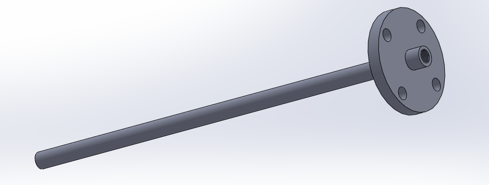
Fig. 3.1: 3-D model geometry (Classical Thermowell)
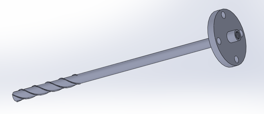
Fig3.2: 3-D model geometry (Helical Strake Thermowell.)
Boundary conditions:
The boundary conditions inputted on the FEA model are as follows:
- Self-weight of the model is considered as standard Earth gravity load in downward directions.
- Pressure due to velocity (taken 3.5m/s2) of water.
- Fixed geometry at the flange due to welding of the thermowell to the flange.
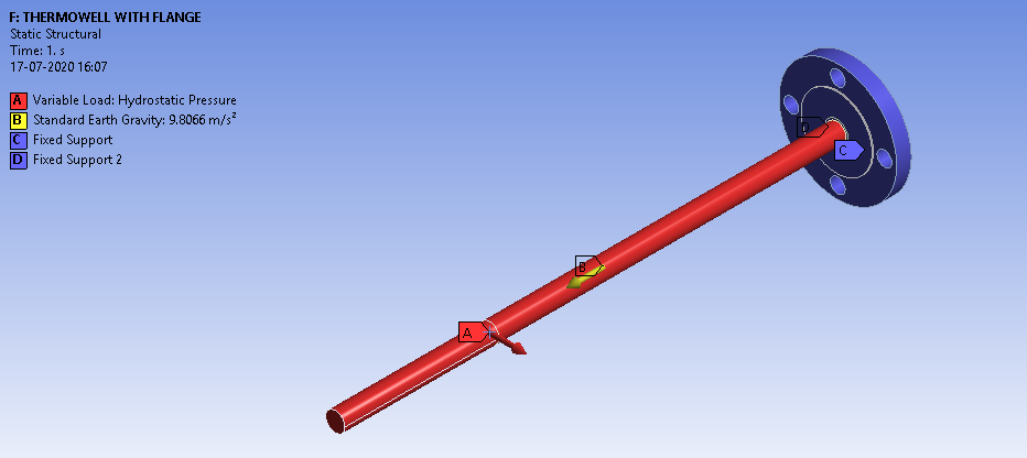
Figure 4.1: Boundary condition on classical thermowell.
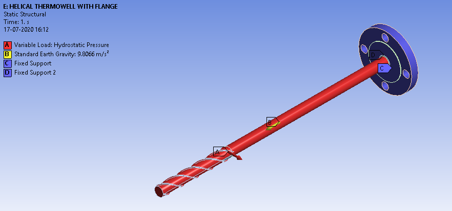
Figure 4.2: Boundary condition on helical strake thermowell.
Results:
Deformation plots for classical and helical thermowell are shown in figure5.1 and figure 5.2 respectively. Elastic equivalent strains for classical and helical thermowell are shown in figure 5.3 and figure 5.4 respectively.
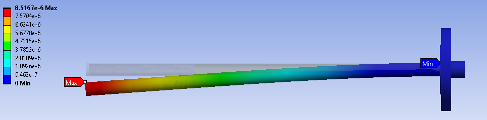
Figure 5.1: Deformation plot for classical Thermowell
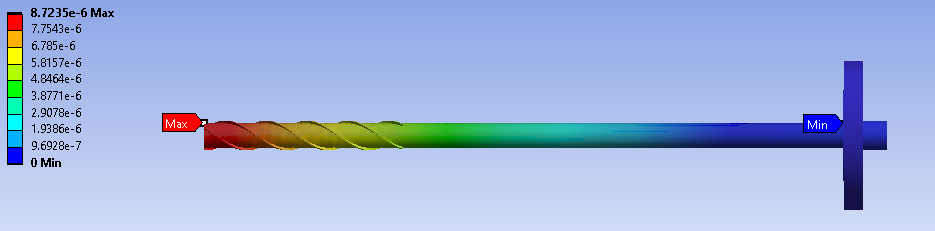
Figure 5.2: Deformation plot for helical strake thermowell.
Figure 5.3: Equivalent Elastic Strain plot for classical thermowell
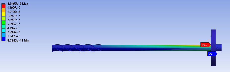
Figure 5.4: Equivalent Elastic Strain plot for helical strake thermowell.
The thermowell with helical strakes demonstrates no regular vortex shedding as compared to classical thermowell. Turbulence was observed in classical thermowell. However, no turbulence was observed in helical straked thermowell. Turbulent kinetic energy plots are shown in figure 7.5 and figure 7.6. The strakes sufficiently disturb the flow in the wake region such that no vortex can form. The strakes also encourage cross-plane flow behaviour along the thermowell length to an extent that was not observed with the classical thermowell, thus interfering with the vortex formation.
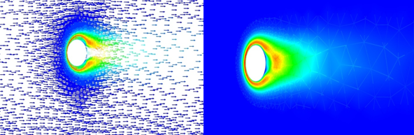
Figure 5.5: Turbulent kinetic energy plot for classical thermowell (Two Dimensional).
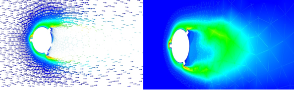
Figure 5.6: Turbulent kinetic energy plot for helical strake thermowell (Two Dimensional)
Inference of Analysis:
| Classical thermowell | Fail |
| Straked helical thermowell | Pass |
PRACTICAL ANALYSIS
Process conditions:
- The thermowells are suspended in a nozzle which has an Electromagnetic Flowmeter installed to measure the flow of water in the pipe.
- The immersion length of the thermowells is 200mm on a 2” 150# RF nozzle.
- A Pen Vibration Meter is used to note the readings of vibration in velocity RMS value.
- The environment conditions were a temperature of 30.8°C and relative humidity of 55%.
Result Obtained:
The following results are obtained for each case of Classical and Helical straked Thermowell:
| Classical Thermowell | |||
| Master Reading | Eq. Master Velocity | Eq. Test velocity | Vibration |
| (m3/h) | (m/s) | (m/s) | (m/s) |
| 604.70 | 3.34 | 1.33 | 0.2 |
| 701.29 | 3.91 | 1.55 | 0.4 |
| 813.50 | 4.54 | 1.80 | 0.7 |
| 905.23 | 5.60 | 2.00 | 1.2 |
| 1026.34 | 5.77 | 2.67 | 1.6 |
| Helical straked Thermowell | |||
| Master Reading | Eq. Master Velocity | Eq. Test velocity | Vibration |
| (m3/h) | (m/s) | (m/s) | (m/s) |
| 605.62 | 3.34 | 1.34 | 0.1 |
| 712.69 | 3.94 | 1.56 | 0.3 |
| 801.98 | 4.48 | 1.77 | 0.5 |
| 908.76 | 5.01 | 2.00 | 0.6 |
| 1024.03 | 5.71 | 2.26 | 1.2 |
Inference:
The vibration in the present design of helical straked thermowell is significantly reduced by approximately 40% as compared to classical thermowell.